1g 2 Way Switch Wiring Diagram
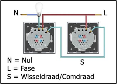
 To switch from two locations youll need 2 two way switches and wire them together in a particular way. There is never a connection betweeen L1 and L2. PrenticeBoyofDerry 7 May 2012.


MK single pole 1 gang 10A 2 way light switches can be wired both one-way and two-way.
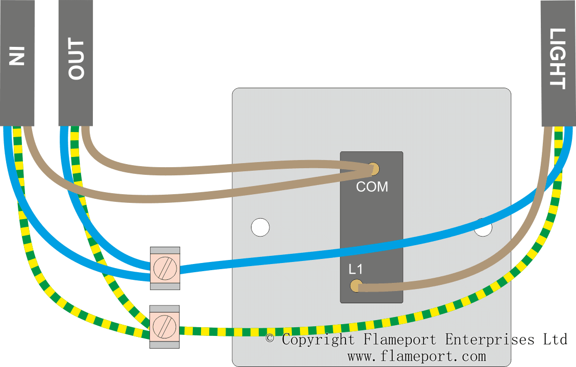
COM 2 WAY 1 WAY as shown. The red wire is connected to the L1 terminal the black wire is unused and should be connected in a plastic terminal block and the earth wire is connected to the earth terminal. Terminals accept up to 6mm² cable. INSTALLATION ALTITUDE 2000 metres Installation EdgeTM socket outlets can be wall or bench mounted. A commonC L1 and L2. 3 x 25mm2 3 x 4mm2 2 x 6mm2 stranded PHYSICAL AMBIENT OPERATING TEMPERATURE 5C to 40C IP RATING IP2XD MAX. 7a For ONE WAY Switching wire the module as follows-Connect LIVE wire to COM terminal Connect SWITCHED LIVE wire to 1 WAY terminal 1 GANG SWITCH EXPLODED VIEW 1 GANG SWITCH 2 GANG SWITCH. K56486 has 4 x 20mm entries 1 on top bottom and each side and is supplied with an earth terminal in the back box. 3 Way Switch Wiring Diagrams Do-It-Yourself-Help throughout 2 Way Dimmer Switch Wiring Diagram image size 502 X 330 px and to view image details please click the image. Two way switching allows you to control a light from two locations. This arrangement is often found in stairways with one switch upstairs and one switch downstairs. Temperature Range-20C to 40 C. This isolating switch can be installed as shown in the diagrams to enable the remainder of the circuit to remain live. 0C to 40 C. The feed cable going to the first switch is connected as follows fig 4. These instructions should be read in conjucntion with the instructions supplied with the fan unit and the latest IEE Wiring Regulations. 2 gang backbox has 5 cable entries 2 on top and 1 centrally on other 3 sides. They are wired so that operation of either switch will control the light.

3 x 25mm2 3 x 4mm2 2 x 6mm2 stranded PHYSICAL AMBIENT OPERATING TEMPERATURE 5C to 40C IP RATING IP2XD MAX.
0C to 40 C. Two way switching allows you to control a light from two locations. INSTALLATION ALTITUDE 2000 metres Installation EdgeTM socket outlets can be wall or bench mounted. 3 Way Switch Wiring Diagrams Do-It-Yourself-Help throughout 2 Way Dimmer Switch Wiring Diagram image size 502 X 330 px and to view image details please click the image. The feed cable going to the first switch is connected as follows fig 4. Temperature Range-20C to 40 C. This arrangement is often found in stairways with one switch upstairs and one switch downstairs. A commonC L1 and L2. - COM 2 WAY 1 WAY as shown. If you need to control the lights from three places say you have 3 entrances to a large room and need a light switch next to each one you will need an intermediate switch. These instructions should be read in conjucntion with the instructions supplied with the fan unit and the latest IEE Wiring Regulations. These are often used on a stair case large room with switches by each door. 7a For ONE WAY Switching wire the module as follows-Connect LIVE wire to COM terminal Connect SWITCHED LIVE wire to 1 WAY terminal 1 GANG SWITCH EXPLODED VIEW 1 GANG SWITCH 2 GANG SWITCH. Each standard Switch Module is a 2-way single pole type has 3 clearly marked terminals. 2 gang backbox has 5 cable entries 2 on top and 1 centrally on other 3 sides. K56486 has 4 x 20mm entries 1 on top bottom and each side and is supplied with an earth terminal in the back box. Terminals accept up to 6mm² cable. They are wired so that operation of either switch will control the light.

This isolating switch can be installed as shown in the diagrams to enable the remainder of the circuit to remain live.
0C to 40 C. 2 gang backbox has 5 cable entries 2 on top and 1 centrally on other 3 sides. Each standard Switch Module is a 2-way single pole type has 3 clearly marked terminals. They are wired so that operation of either switch will control the light. Temperature Range-20C to 40 C. The red wire is connected to the L1 terminal the black wire is unused and should be connected in a plastic terminal block and the earth wire is connected to the earth terminal. This arrangement is often found in stairways with one switch upstairs and one switch downstairs. 3 Way Switch Wiring Diagrams Do-It-Yourself-Help throughout 2 Way Dimmer Switch Wiring Diagram image size 502 X 330 px and to view image details please click the image. INSTALLATION ALTITUDE 2000 metres Installation EdgeTM socket outlets can be wall or bench mounted. K56486 has 4 x 20mm entries 1 on top bottom and each side and is supplied with an earth terminal in the back box. These are often used on a stair case large room with switches by each door. - COM 2 WAY 1 WAY as shown. 7a For ONE WAY Switching wire the module as follows-Connect LIVE wire to COM terminal Connect SWITCHED LIVE wire to 1 WAY terminal 1 GANG SWITCH EXPLODED VIEW 1 GANG SWITCH 2 GANG SWITCH. Terminals accept up to 6mm² cable. These instructions should be read in conjucntion with the instructions supplied with the fan unit and the latest IEE Wiring Regulations. If you need to control the lights from three places say you have 3 entrances to a large room and need a light switch next to each one you will need an intermediate switch. Two way switching allows you to control a light from two locations. The feed cable going to the first switch is connected as follows fig 4.


These are often used on a stair case large room with switches by each door.
7a For ONE WAY Switching wire the module as follows-Connect LIVE wire to COM terminal Connect SWITCHED LIVE wire to 1 WAY terminal 1 GANG SWITCH EXPLODED VIEW 1 GANG SWITCH 2 GANG SWITCH. A commonC L1 and L2. 0C to 40 C. Two way switching allows you to control a light from two locations. If you need to control the lights from three places say you have 3 entrances to a large room and need a light switch next to each one you will need an intermediate switch. INSTALLATION ALTITUDE 2000 metres Installation EdgeTM socket outlets can be wall or bench mounted. K56486 has 4 x 20mm entries 1 on top bottom and each side and is supplied with an earth terminal in the back box. - COM 2 WAY 1 WAY as shown. Terminals accept up to 6mm² cable. The feed cable going to the first switch is connected as follows fig 4. Temperature Range-20C to 40 C. They are wired so that operation of either switch will control the light. 3 Way Switch Wiring Diagrams Do-It-Yourself-Help throughout 2 Way Dimmer Switch Wiring Diagram image size 502 X 330 px and to view image details please click the image. The red wire is connected to the L1 terminal the black wire is unused and should be connected in a plastic terminal block and the earth wire is connected to the earth terminal. 2 gang backbox has 5 cable entries 2 on top and 1 centrally on other 3 sides. This arrangement is often found in stairways with one switch upstairs and one switch downstairs. These instructions should be read in conjucntion with the instructions supplied with the fan unit and the latest IEE Wiring Regulations. Each standard Switch Module is a 2-way single pole type has 3 clearly marked terminals.